
In this article:
- Special adaptations of digital servo valves for new A350 airplane test system
- Unique high performance digital servo valve including fast EtherCAT fieldbus and interfaces for different external sensors
- Collaboration between teams resulted in reduced cabling and improved flexibility
The Application
In 2009 the engineers from Airbus’ High Lift Test Centre in Bremen, Germany needed a system to test the landing flap systems for the new Airbus A350 airplane. The new Airbus A350 has two landing flaps at each wing that are stressed by high aerodynamic forces. These forces need to be simulated during the test.
The motion control system for testing the landing flaps of the plane was to be mounted in a metal framework. The load frames are connected to 6 hydraulically-operated servo cylinders and follow the flap motion. Pneumatically-operated plunger cylinders mounted on metal frames would simulate the load. The 6 hydraulic cylinders are located so that the range of motion and load the forces are spread as equally as possible and each has closed-loop position control.
A standard industrial PC with a sampling rate of 1000 Hz, employs an EtherCAT field bus to controlling these 12 axes (6 for each flap) as well as the other actuators. Since both the absolute value and the direction of the aerodynamic forces are changing during the test, the metal framework with the pneumatic cylinders must follow predefined spatial motion. The force and motion profiles are described by coordinates of the plane. From these coordinates the PLC calculates in real time the required cylinder strokes during the motion.

Principal sketch of landing flap system
Yellow actuators driven by Moog Servo Valves – 12 linear axes/valves for spatial motion of the metal frame,1 rotary drive/valve to load drive shafts and gears
In addition to spatial motion of the metal frame there is another force applied to the system to simulate the load torque to a drive shaft system. The motion for this subsystem required a highly specialized closed loop proportional valve. The testing of the motion of landing flaps is controlled by a combination of rotary drive, drive shafts and gears. The test system has an additional rotary drive to apply load torque to the rotary drive of the plane.
The Request
The Project team members for creation of the test system were Airbus Bremen, Hycom Hydraulic Systems from The Netherlands, the German engineering office IgH and Moog in Germany. Hycom Hydraulic Systems were responsible for designing and building the hydraulic system and IgH for implementing the motion control for the system.
As a market leader in high performance servo control and with product engineers with extensive experience in the aerospace test industry, Moog was selected to design and build highly specialized servo valves to fulfil the customer’s unique requirements. From the beginning it was clear that the application called for Moog’s Digital Valve Technology and special interfaces would be needed.
In addition to the high performance hydraulic functionality, the required valves needed specific features and characteristics:
- EtherCAT field bus interface
- Analog inputs for pressure transducers
- An interface for an incremental position encoder
- A new analog input for force control by a strain gauge
- Special wiring for the 11-pole + PE connector
The Solution
The Moog Digital Servo Valve Series D671 with integrated I/O interfaces was determined to be the right solution to provide the closed-loop axis control in the flap test system. This valve, equipped with an EtherCat fieldbus interface, controls the axis positions via the central PLC.
Each valve actually controls two key functions: on one hand it acts as a bus coupler to allow simultaneous reading of cylinder pressures and on the other hand it switches the external safety valves (via the EtherCAT bus) to control clamping/braking of the cylinders or to by-pass the rotary drive.

Moog valve as multi I/O device

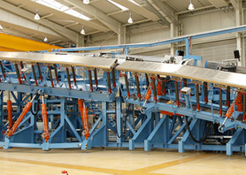
Metal framework with hydraulic cylinders
Source: Courtesy of Airbus Bremen

Cylinder with Moog D671 series valve
Source: Courtesy of Airbus Bremen
Analog Input X12 for Sensors with Resistive Bridges
In order to avoid additional wiring, the Airbus team requested that Moog develop an input on the Moog valve to allow interfacing of a force sensor. This was challenging as an interface for sensors of this kind had never been developed. The solution developed by the Moog team was to implement the connector on the OBE, more specifically a 4-pin female M8x1 connector located at the front of the electronics housing below the analog inputs X5, X6, X7. This solution greatly increased the flexibility of Moog’s digital valves as the number of possible variants that could effectively use this new analog input was high. Think about X12 valves with sensors with resistive bridges in this case but there are many other possibilities such as:
- Force measuring gauge
- Pressure sensors without electronics
- Strain measuring gauge

New analog input for sensors with resistive bridges
| Differential input resistor | 40 kOhm |
| Input resistance to internal Reference (2 V) | 20 kOhm each input |
| Supply resistor (low end) | 200 Ohm |
| Sensor supply | 12 V |
| Maximum input voltage for 100% A to D converter input | +/- 20 mV |
| Resolution A to D converter | +/- 12 Bit |
| Typical noise with shielded wiring | < 0.1 % |
| Cable break detection | Current consumption measured low side |
Technical Data of Analog Input X12
| Pin | Pin Assignment | Special function | Bridges |
| 1 | Bridge to 7 | - | |
| 2 | Ground (Bridge to 5 and 10) | - | |
| 3 | Enable input | - | |
| 4 | Analog command input (not used) | - | |
| 5 | Ground (Bridge to 2 and 10) | - | |
| 6 | Actual valve output (not used) | - | |
| 7 | Bridge to 1 | - | |
| 8 | Digital output 1 (valve status); 24 V and 1,5 A | If enable and supply ok, valve ready; switching of external valve | |
| 9 | 24 V DC power supply | - | |
| 10 | Ground (Bridge to 2 and 5) | - | |
| 11 | Digital output 2; 24 V and 1,5 A | Controlled by event handler; switching of external valve | |
| PE | Protective earth connection | - |
Special wiring 11+PE-connector X1
Special Wiring on Main Connector X1
In this application, safety functions in the hydraulic system are critical and required external on / off valves. To reduce wiring expense and the need for junction boxes for each valve, Airbus asked Moog to offer a solution. Moog recommended using the two digital outputs to switch the external valves and for cabling reduction a special wiring with internal bridges was created.
For the first external valve the Digital output 1, which is the “valve ready” signal, is used. This output can be energized with the enable signal at Pin 3. The digital output 2 is controlled via the EtherCAT fieldbus. The logic behind this second output is programmed in the valve internal event handler.
These two digital outputs supply the external on / off-valves with 24 V and 1.5 A. In the test system this unique functionality is used for braking or clamping the cylinders. For the rotary drive only one output is used to switch an external by-pass valve.
The Result
The combination of a fast fieldbus system, a servo valve with integrated I/O’s and a hydraulic servo cylinder results in a high performance automation solution and offers many benefits:
- Components are easy to change because the “intelligence of the system” is not programmed in the firmware of the components, but in the industrial PLC system.
- The coincidental use of a hydraulic servo valve as I/O component for typical actuating elements and sensors on hydraulic cylinders without using these signals not only for itself, is highly beneficial for open automation solutions.
- Minimal cabling which reduces expense, complexity and space requirements
- Local parameterization offers users greater flexibility especially when compared with previous local axis controller solutions

Moog Servo Valve with rotary drive during the test phase
Author
Thorsten Köhler started at Moog GmbH in 2007 as Product Engineer for hydraulic valves, with responsibility for pilot operated valves. At the end of 2008 he changed his role to become an Applications Engineer within the Control Solutions organization, Europe, where he helps to create customized solutions for a wide range of customers with applications in the injection molding machines, presses, test systems and other special machinery markets. He studied Mechanical Engineering at the University of Furtwangen, Germany.