
Moog recently completed a challenging and high profile project that required great expertise in electric actuation as well as the highest level of project management to design. The project involved creating a control architecture for the actuated elements of a moving roof on the Centre Court at Wimbledon - unarguably one of the most famous tennis events in the world. In 2007 it was viewed in 748.4 million TV homes. This motion control challenge required that Moog’s world-class products work securely, quietly, speedily, safely and accurately and that the project was on-time for the 2009 Championships where it would be under the scrutiny of the entire viewing world.
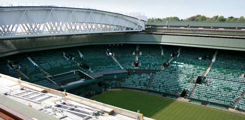
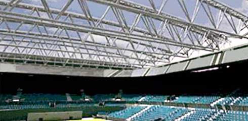
Wimbledon Centre Court view at roof level.
The project involved supplying 148 axes of control with products and software for closed-loop control for the roof movement. Engineers from United Kingdom, Germany, Italy, Ireland and the United States worked together from definition of requirements to final implementation and on-going support to provide a truly collaborative solution for a very special customer.
The Project Definition
Take a world renowned sporting venue, steeped in heritage and tradition, one that is home to a sporting championship seen in 750 million homes, followed by more than 10 million internet users making 46 million visits online and spending an average of 70 minutes each with eyes glued to the hallowed turf. That’s Wimbledon.
Even non tennis fans will know that the image of the Wimbledon Championships at the All England Lawn Tennis Club can be spoiled by the realities of the British weather. With the popularity of the game growing and increasing numbers of spectators, including the world media taking an interest, uninterrupted play became a big priority. So it became clear that a new solution was needed, and that solution was to put a roof on the world famous Centre Court at Wimbledon. That’s when a world leader in motion control, Moog, was called in to help make the vision a reality - because this project was expected to be challenging.
Initial discussions took place in 2004 when Moog and a number of specialists were approached to answer the complex control problem of an actuated moving roof. Initial discussions considered the use of hydraulic actuators but Moog engineers, in discussion with the design teams concluded that these would not be the perfect solution: noise and vibration from many hydraulic power units might be an issue and even the slightest risk of oil seepage onto the grass wasn’t worth taking.
It was then that Moog expertise came to the fore. “Electric actuation was the answer and we had a solution that met both technical and architectural requirements. The system would also be extremely quiet and remove the risk of oil seepage – a perfect solution”, explained Ian Bartlett, Project Manager.
“With expertise in both hydraulic and electric technologies, we are able to be unbiased and provide a technology-neutral opinion in such situations, and for this project an all electric approach was proven to be the most appropriate solution,” he said. “The architects wanted a roof that would occupy minimal space in the open position, partly to allow maximum sunlight access to the grass and partly to ensure the same level of ventilation was afforded to the space. The Moog solution was one of a number that enabled the architects to achieve their objectives without compromising the functional performance of the system.”
Project Implementation
The collaboration along with Moog technical know how and world-class products ensured that the new moving roof at Wimbledon was delivered on time and to great critical acclaim. “Other than the obvious functional performance pressures such as the speed and accuracy of deployment, there was also the small matter of ensuring that the roof was completed and tested in time for this year’s Championships,” added Bartlett.
In a complex hierarchy of contractors, Galliford Try, who were appointed in 1973 to look after the site and have also been managing the master plan since 1994, instigated the phase to install the retractable roof. At the same time major changes to the Centre Court structure and facilities to accommodate the new roof were implemented. Watsons were appointed to carry out the major steelwork and SCX were contracted to work on the mechanical components. All of this infrastructure was brought “to life” by Moog’s electric products. Moog supplied the high performance electric control system comprising of electric actuators, servomotors, servodrives and closed-loop controllers. Additionally, Moog worked with a partner to deliver the supervisory and data acquisition system. A total of 148 axes of control have been supplied by Moog as well as the 40 control cabinets mounted on the roof trusses and main control desk housed within the Centre Court control room. All these products and software operate together to allow over 1,000 tonnes (1,102 US tonnes) of steel to move safely above 15,000 spectators.
How the Roof Works
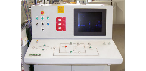
Main Control Panel in test
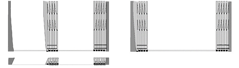
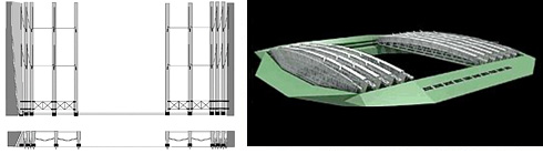
The new roof works on a principle similar to a folding fabric concertina - with metal ribs or “trusses” supporting a translucent industrial fabric. “The trusses are basically inverted triangles, which are supported by the end arms and set into precise motion by electric actuators which form a structural yet moveable part of the roof. The accuracy of movement has to be virtually pin point at both ends of the trusses,” explained Ian. With this design, the roof can be folded into the ends of the building, with the translucency giving the court an open feel when closed.
The retractable roof is made up of 9 bays of tensioned fabric divided into two sections (North and South). The northern section has 5 bays, with 4 in the south. Each bay is captivated on either side by a steel truss (10 trusses in total) spanning the 77 m (253 ft) wide court with approximately 5,200 square metres (55,972 square feet) of fabric keeping the rain out and allowing the light in. The ends of each truss are supported by a wheeled carriage or “bogie” which moves along a track positioned on the newly installed ‘fixed’ roof of the Centre Court. The roof takes eight minutes to close and if that’s being done because of rain, court covers will protect the grass in the usual way while the closure is in progress.
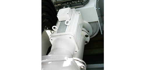
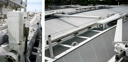
Bogie Motor on track
The roof has 5 basic modes of operation, each activated by one button:
1. Move to Park Position
The Roof is in two “halves”, the North and the South sections. For most of the year both sections are stored at the North end of the Centre Court.
When not in use for the Championship, the south roof sections are “Moved to their Park Position” at the north end of the stadium for storage. This park position allows the maximum sunlight to reach the court, particularly during the winter months. The south roof unlocks from the fixed roof and begins its travels towards the north section.
The PLC gives a target position to the Moog Servo Controllers (MSC) responsible for the movement of the “leading” truss. Each truss is controlled by an MSC controller on each end. The master MSC generates a position command profile and this is used by both sides to control the movement of the bogies in closed-loop position control. The feedback position of all the trusses is measured to within 0.1 mm (0.004 in) over the entire length of the roof.
The master continuously monitors the following and skew errors and adjusts the command position to maintain the position accuracy across the roof. The lead truss also sends an assisting torque to the following truss bogies so that all the trusses move as one at 100 mm/s (3.94 in/s) towards the north sections. When the south roof nears the north roof it slows and creeps gently into the final position. The two sections then lock together and remain in position until they are needed again.
2. Move to Championship Mode
.
During Championship mode, the reverse process happens and the south roof sections move down to the south and attach once more to the fixed roof. At the end of the movement after the south section is locked into place the trusses are within 0.5 mm (0.02 in) of their desired positions.
3. Deploy/Close the Roof
Each Half Truss is controlled by its own Control Panel. Each MSC controls 4 off End Arms, 2 off Restraint Arms and 2 off Bogie motors in synchronization control. The End Ams and Restraint Arms are controlled in Position control, the bogie motors are controlled in torque mode. The MSC’s controlling each half truss communicate with each other and thus the whole truss is synchronized.
When the decision is made to close the roof, the roof begins to deploy one truss at a time on both the north and south sections. The truss is deployed by the bogies and the end arm assemblies. The end arm assemblies look like giant inverted hinges which open up from a very deep narrow “V” into a wide shallow “V”. During the movement the point of the V moves up and the ends move out thus pushing the top of the deploying truss away from its neighbor. This movement is controlled using four end arm actuators on each side. Each actuator is capable of pushing and pulling with a force equivalent to 35 tonnes (38 US tonnes) at its rod end. The actuators are connected to the end arm assembly so that there is a large mechanical advantage.
The position of all the end arm actuators are controlled in closed-loop position control using its own inbuilt absolute encoder. All 8 actuators are synchronized by the MSC controllers. However, as the end arm assembly deploys the mechanical advantage and lever ratio changes, the MSC compensates for this change by using a look up table to check the current actuator position against a linear deployment position. This check is important because not only does the MSC have to keep the end arm actuators synchronized, it also has to position the bogie directly below the top of the truss to keep the truss in a vertical position. Across the centre of each roof section are 4 restraint arm assemblies, each with its own actuator. These help maintain the shape of the truss across the length and ensure that the trusses meet square when the north and south sections are fully deployed. These actuators also work through a non-linear linkage and they too have to be synchronized with the end arms and bogies.
End Arm Actuator | Restraint Arm Actuator Full Deployed
Once a truss is deployed the restraint arms and end arms are locked and the next truss deploys. While the next truss deploys a torque is sent to the bogie motors on the already deployed truss so that it moves in unison. In this way when the last truss is deploying the actuators and motors on that truss uses roughly the same forces as the first truss deploying on its own.
4. Roof Deployed
The roof retracts in a similar fashion to the deployment.
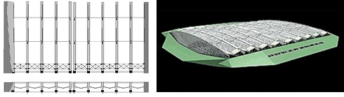
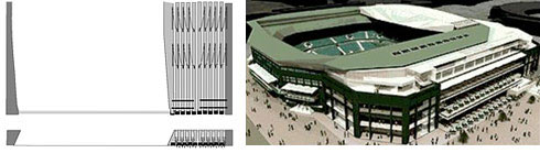
View from below (without roof cloth)
5. Sunshade Mode
The leading truss on the southern roof is deployed to provide shade over the Royal Box. When the roof is in this position it can be either deployed or retracted, depending on the whims of the British weather.
The Benefits of the Moog Solution
The roof has been designed to work securely, quietly, speedily, safely and accurately. In a sense, the less it’s noticed the more it is achieving its technical objective. The translucent nature of the roof makes it easy to forget it’s there when it’s fully deployed.
This project involved collaboration with engineers from our facilities in the United Kingdom, Germany, Italy, Ireland and the United States to design and build a motion control solution that met all of the stringent requirements of this high profile project. Everyone at Moog has felt a huge sense of pride at working on this prestigious project, not just those who have been involved in bringing it to fruition. It demonstrates the partnership approach we bring to complex situations where many contractors are involved. A key objective was to ensure that while the finest technology was employed, the heritage of the venue was preserved. But one tradition that even die-hard Wimbledon fans won’t miss this year is the phrase: ‘Rain stopped play’.
Author
Ian Bartlett worked as a Senior Project Engineer working on a number of Electro-Hydraulic applications, becoming Engineering Solutions Manager for the Industrial Engineering Group at Moog in Tewkesbury, England (MCL) with responsibilities for the engineering team. Since 2009, as part of the European Control Solutions Organisation, Ian now has responsibility as the European Programme Manager for Power Generation as well as the MCL Local Engineering Coordinator role. Ian has a background in both electrical and mechanical/hydraulic systems having studied for his Degree in Electrical Engineering.
Simon Furnell, Moog Senior Applications Engineer has been with the company since 2001. Simon has been involved in the project since the first telephone enquiry until the final sign off and has played a key role in the early design stages, development of software and testing of the roof, often working in the difficult conditions the British weather can throw at you. Simon has a B.Eng in Mechanical Engineering and a MSc in Fluid Power Systems, both from the University of Bath.