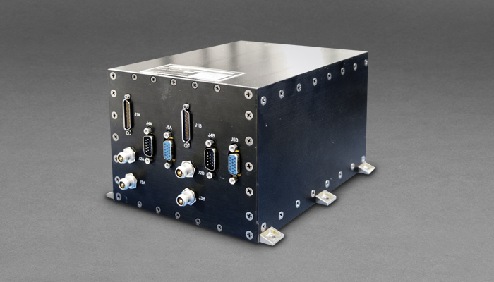
Gimbal Control Electronics (GCE)
Features:
- Use pulsed discretes to turn on active side
- Spacecraft Interface via dual redundant Mil-STD-1553B buses
- Uses +5 V and ±15 V DC/DC Converters with separate EMI Filter
- Motor drive has micro-stepping capabilities
- Motor uses half Bridge driver and QuadPower Mosfet to drive the motor
- Provides 8 Iset power points for each motor
- Provides Encoder LED bias current selectable 20 mA or 35 mA
- Provides SOH Monitoring circuit, 12 bit ADC (internal voltages and motor current)
- Provides 1 mA constant current for PRTs and Thermistors (8)
Mass, Power, Dimensions
- 3.8 kg
- 24 to 35V Input
- 12 W Nominal per active side (excluding motor current)
- 190 mm x 158 mm x 118 mm
- -10°C to +40°C Operational Temperature
- -20°C to +50°C Qualification Temperature
Reliability Features
- All Parts SEL Immune
- 100% Dual Redundant
- The GCE contains primary and redundant incremental encoder interface circuits
- The GCE contains two primary and two redundant 3 phase motor drive outputs.
- >15 kRad Standard (100 kRad Option)
- Conduction Cooled Design
- All Parts MIL-883B
Options
- Single String Version
- RS-422, RD-485, or LVDS interface
- Custom Command & Telemetry ICD
- >2 Motor Versions
- Custom Form Factor
The Moog Broad Reach Gimbal Control Electronics (GCE) system controls and drives two types of dual axis redundant actuators. The system contains two primary and two redundant motor drive outputs. These motor drive outputs control and drive small, three phase Wye, six state, and permanent-magnet actuators. The GCE contains two primary and redundant incremental encoder interface circuits. The GCE communicates with the spacecraft via a dual redundant MIL-STD-1553B bus. The spacecraft provides the 31VDC nominal voltage and the side enable pulsed discretes. The GCE assembly consists of two identical Controllers circuit boards, two identical Motor Driver circuit boards, two identical DC to DC converters boards, two Backplane boards and the chassis.
The GCE implements programmable micro-stepping to reduce jitter in increments of 1,2,4,8,16,32 or 64 microsteps/cardinal-steps. Current in all phases driven as a sinusoid for smooth movement. Optical encoder feedback is provided but not required to command motor movements. Positional feedback, detection of skipped steps, and state of health (SOH) current for each motor along with 8 variable power settings per motor are implemented.