Fastact G Servomotors are known as the choice for highly dynamic servo applications where positioning times of 30 msec or less are often the norm. Moog continues to enhance this product line with additions such as the new Fastact G Size 1 motor that adds the 40 mm flange size to the existing product range and improvements such as expanded encoder feedback options.
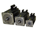
In response to needs in the marketplace, Moog developed the G4-1, a low voltage (325V) servomotor that comes with the standard options such as a brake, encoder/resolver choices and various shaft options. All this flexibility comes with the exceptional performance as shown in table 1. Now The G-Series range goes from a size 1 (40 mm flange size) to a size 6 (190 mm flange size) with the following performance range:
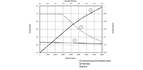
- Continuous stall torques ranging from 0.15 [1.3] to 77 [681] Nm [lb.in],
- Peak Torques from 0.5 [4.4] to 240 [2124] Nm [lb.in] and
- Continuous power from 0.13 [0.18] to 12 [16] kW [hp].
| Category | Symbol | G4-1 | Units | ||
| Stack length (in mm) | - | L20 | L40 | L60 | - |
| Nominal Torque, continuous duty, locked rotor | MO | 0.15 [1.3] |
0.27 [2.4] |
0.37 [3.3] |
Nm [lb.in] |
| Nominal speed | nN | 9000 | 6000 | 6000 | rpm |
| Max torque | Mmax | 0.5 [4.4] |
1 [8.9] |
1.5 [13.3] |
Nm [lb.in] |
| Nominal torque, continuous duty, nominal speed | MN | 0.14 [1.2] |
0.2 [2.1] |
0.3 [2.7] |
Nm [lb.in] |
| Output power, continuous duty, nominal speed | PN | 0.13 [0.18] |
0.15 [0.20] |
0.19 [0.25] |
kW [hp] |
| Rotor inertia (resolver included) | J | 0.023 [0.2] |
0.045 [0.4] |
0.068 [0.6] |
Kgcm2 [lb-in.sec2 x102] |
| Torque constant | kT | 0.17 [1.5] |
0.34 [3.0] |
0.46 [4.1] |
Nm/Arms [lb-in/Arms] |
| Thermal time constant | tTh | 600 | 650 | 700 | sec |
| Winding resistance at 25°C (phase to phase) | Rtt | 23.0 | 34.8 | 37.0 | Ohm |
| Weight (without brake) | m | 0.55 [1.2] |
0.68 [1.5] |
0.82 [1.8] |
Kg [lb] |
Table 1 - Performance Specification for Standard Models
Notes:
- Motor performances as measured with Moog's servodrive of proper size
- Rotor inertia: with resolver, no holding brake


Expanded Feedback Options for Greater Flexibility
With the growing requirements for encoder feedback in industrial markets, Moog is now offering various encoder feedback options on our high-performance Fastact G Servomotors. Our application experts work with customers to identify which technologies are the best for their applications.
Selecting Resolver or Encoder Based Systems
When the environment has hot, very cold, humid, oily, high vibration/shock, dusty or other beyond normal industrial conditions, a resolver-based system is the preferred choice.
When precise positioning, smooth torque and stable velocity control are top priorities for the application, the encoder-based system is the preferred choice. Encoders typically have all their electronics onboard, minimizing interconnections, but limiting operating temperatures.
In determining whether to use a Moog servomotor with a resolver or encoder, close consideration of the application under the characteristics shown in table 2 is required. All factors must be balanced for the right design fit.
Specifications: Encoders vs. Resolvers
| Category | Resolver | Encoder |
| Angle measurement | Absolute | Absolute/Incremental |
| Absolute resolution | 16 bits | 13 bits |
| Incremental resolution | N/A | 10,000 lines/revolution |
| Accuracy (arc minutes) | 4 to 40 | 0.25 to 6 |
| Electronic interface | R/D converter | Direct |
| Noise immunity | Sensitive | Best |
| Output signal | Analog | Analog/Digital |
| Construction materials | Robust | Fragile |
| Weight | Heavy | Lighter |
| Inertia | High | Low |
| Longevity | Very High | High |
| Shock/vibration | Rugged | Limited |
| Temperature Range | -50 ºC to +150 ºC | -20 ºC to +100 ºC |
| Contamination | Immune | Vulnerable |
Table 2: Encoder v Resolver Application Considerations
Selecting Encoders
In determining which type of encoder to use, the initial choice is to determine whether to use an absolute or incremental encoder.
Incremental encoders have output signals that repeat over the full range of motion. It is important to understand that each mechanical position is not uniquely defined. When the incremental encoder is turned on, the position of an incremental encoder is not known since the output signals are not unique to any singular position.
Absolute encoders report absolute positional information. When powered up, it does not require a home cycle, even if the shaft was rotated while the power was off. If an absolute encoder is chosen, the further choice is whether to use a single-turn (unique position information within one revolution) or multi-turn (unique position information beyond one revolution) absolute encoders.
Table 3 below shows the encoder option sizes available by servomotor front flange sizing.
| TYPE | MFG | Size 1(40 mm) | Size 2 + 3 (55 + 70 mm) | Size 4(100 mm) | Size 5 + 6(140+190 mm) |
| Incremental | STEGMANN | - | CKS 36 | CNS 50 | CNS 50 |
| ABS Single Turn | - | SKS 36 | SRS 50 | SRS 50 | |
| ABS Multi Turn | - | SKM 36 | SRM 50 | SRM 50 | |
| Incremental | HEIDENHAIN | - | ERN 1185 | ERN 1387 | ERN 1387 |
| ABS Single Turn | ECN 1113 | ECN 1113 | ECN 1113 | ECN 1313 | |
| ABS Mutli Turn | EQN 1125 | EQN 1125 | EQN 1325 | EQN 1325 |
Table 3. Encoder options by servomotor flange size
Author
Andrew Barrett, B.E.(electrical), M.Eng.Sc. (control electronics), MBA, is a Product Line Manager for Moog’s Industrial Servomotors. He brings 15 years of experience in engineering, operations and product line management, gained during a career with several multinational companies.