One of the most important services Moog offers is the ability to customize its products to improve machine performance and provide solutions to motion control problems that our customers are facing. This requires an advanced knowledge of system design and machine applications, as well as experience in designing and building precision products. One example of this capability is the process of customizing the spool null cut in Moog’s Servovalves and Servo-Proportional Valves. It is a critical process for customers as this customization provides for the highest performance and precision of motion control. While many engineers are aware of the importance of the precision of the spool cut they may not be aware of the process Moog application engineers use to define a null cut configuration to solve system or machine problems.
There are many options for customizing a spool null cut to optimize machine performance for a specific application. This article discusses some of the following typical configurations: critical center spool (axis cut), open center spool (underlap), closed center spool (overlap) and dual gain valves.
Critical Center Spool Valves
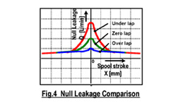
Critical center spool valves, also called “Axis cut or Zero overlap valves,” are the most popular valve configuration for high performance Moog Servovalves. This describes a product where the spool lands align with the edge of the ports so that the control flow is zero at null and there is no dead band in the null region. Axis cut valves are suitable for position control servo systems because they deliver seamless control flow to an actuator and give higher pressure gain, leading to increased actuation stiffness.
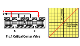
The axis cut valve may not be suitable for some applications. One example is a servo system that is not stable due to poor damping. Another involves situations where there is a strong requirement to save energy and the null leakage of the axis cut valve is unacceptable. In these situations, other null cut customization options are available.
Open Center Spool Valves
Open center spool valves also named “Underlapped valves” describes a product where each edge of the spool does not fully cover the corresponding control port in the null position. When the valve is at null this arrangement results in a flow from the supply port, across each control port to the return port.
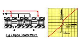
Underlapped valves may be suitable in the following cases:
- Machines that lack adequate damping. Underlap can be helpful because the increased flow versus port pressure characteristic in the null region gives a natural damping effect. The typical underlap to improve system damping is normally 2 ~ 3% of rated control flow
- Machines where the pressure gain of the axis cut valve is too high to give a reasonable gain distribution in the closed loop. Underlap may be used to achieve a suitable pressure gain.
- Machines with a hydraulic servo-drive where there is a need to compensate for motor leakage by maintaining high strut port pressures to achieve better stability and higher stiffness at null. In this case, the metering edges of the two control ports to the return port are overlapped so that at null the strut port pressure is increased.
- Machines that require the actuator to be manually overridden in case of power loss. An underlapped valve permits flow between two control ports of the open center valve. In this case safety, not performance, may be first priority.
On the negative side, this null cut configuration increases the null leakage with a resulting energy loss. This can be minimized by using so-called load sense systems, which unload the supply pressure during the no-load condition when the valve is at null.
Closed Center Spool Valves
Closed center spool valves, also named “Overlapped Valves”, describes a valve in which the spool land overlaps the edge of the port and completely block the ports in the bushing, when the valve is centered.
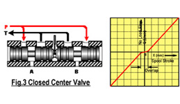
This is not commonly used in critical servo systems because of the negative effect of the resulting dead band, but the following are some conditions where there are advantages to using this form of customization:
- In systems where axis cut valves do not work well due to high leakage through the diametral clearance between the spool and sleeve. Here a very small overlap may be required.
- For larger servovalves the null leakage of an axis cut can represent an unacceptable energy loss. To reduce this, a 3% overlap valve is frequently used.
- When operator and machine safety is critical. In the event of power loss or no hydraulic pressure, the load can be held by an overlap valve, blocking the control ports.
- In Servo-Proportional valves without a bushing where rapid erosion of the critical flow control edges in the body can occur. Overlap is used together with electronic overlap compensation.
Dual Flow Gain Valves
A Dual Flow Gain Valve is another kind of customization where the valve has a non-linear characteristic curve. Typically, this valve has lower flow gain in the null region permitting higher system gain, but beyond a certain flow the higher flow gain permits high speed traverse. Typical examples of the application are electric discharging machines and material handling robots.
About the Author
Nobuhiro Ohtaguro has worked for Moog in the Pacific for over 30 years. He started his career as an application engineer and progressed to Engineering Manager in Moog Japan. He also worked in Australia and Singapore as a Special Project Manager for 3.5 years. Today he provides technical advice and training to the engineers in the Pacific Moog subsidiaries.