In this article:
- Moog’s 60+ year commitment to innovation leads to a new standard in high performance mechanical feedback servo valves.
- Three keys to servo valve longevity include use of carbide ball construction, ball-in-hole design and the brazing process.
- Moog engineers define long life for a Moog Servo Valve as above one billion cycles.
Moog engineers employ new materials, designs and manufacturing process to maximize Servo Valve life expectancy

Whether it’s in material testing, structural testing, simulation or plastics molding, the servo valve plays a critical role in the performance of a hydraulic positioning, velocity or pressure control application. And with rising operational costs and increasing pressure on design engineers to achieve greater results in machine performance, it is critical to evaluate each component’s impact on the total life cycle cost of the machine.
William Moog’s revolutionary feedback mechanism design
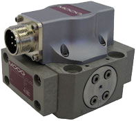
Moog Mechanical Feedback Servo Valves incorporate a feedback mechanism that precisely determines the position of the spool in the valve and stops it at a position that is proportional to the electrical input of the valve. This technological breakthrough revolutionized the industry when it was made commercially viable by William C. Moog in 1951, and it has made Moog synonymous with servo valves more than six decades later.
A history of Moog Servo Valve innovation
During the past 61 years, Moog engineers have followed a consistent pattern of servo valve refinement and technological improvement. In 1960, the Moog 071 Series was introduced, ushering in the first dry air gap, nozzle/flapper torque motors. Two years later, Moog engineers developed the 073 Series of high response industrial valves. And in 1967, the 076 Series was introduced for higher response and lower leakage, quickly becoming the world standard. This innovation featured a square body, a tapered bushing that allowed field-replaceable pilot filters and a tube filter.
As Moog modified the servo valve throughout the 1970s and 1980s—with contoured body design and even smaller spool diameters—reducing costs became a key driver for subsequent designs. In 1998, the company introduced the G761-3001 Hydraulic Servo Valve that includes a host of design advantages including a disc filter, square body, single piece flapper/wire and perhaps most critically, a carbide ball that replaced the traditional steel material used for decades (and still used by competitors). While this carbide technology was first developed in 1994, the G761-3001 Servo Valve was where it truly became a mainstream technology.
This design set the new standard for Moog’s industrial high performance servo valves.
Today’s incredibly wide range of dynamic and precise applications often make it difficult to pinpoint the key performance attributes that deliver high performance over a long life. While most manufacturers have defined long life in the millions of cycles, Moog engineers had a different standard in mind: above one billion (1,000,000,000) cycles.
Ensuring a significant increase in the life expectancy of a servo valve begins in its design, manufacturing and construction methods.
Three keys to servo valve longevity
Within the hydraulic servo valve, there are three critical design aspects that lead to increased longevity, minimal unplanned downtime and ongoing, reliable performance. These include:
- Use of carbide ball on the feedback mechanism
- Use of ball-in-hole design in the spool
- Use of brazing to bond the ball to the wire
After one billion test cycles, the stainless steel ball exhibits visible wear. Carbide and sapphire do not. Moog uses the carbide ball for its proven performance and long life. The carbide material also has the advantage of enabling the feedback mechanism wire to be bonded through a brazing process. This provides even greater reliability in industrial environments.

Key #1: Carbide ball construction
Despite using precision machining processes over the years, servo valve designers discovered that premature wear of the ball in the feedback mechanism degraded the valve’s performance. Most early designs incorporated a stainless steel ball on the feedback mechanism that would wear out over time. Since the 1990s, carbide and sapphire materials have been introduced to replace stainless steel and provide extended protection to the ball. It is important to note that although sapphire is much more expensive than carbide, there is no correlation between cost and performance.
In fact, Moog R&D evaluated the wear characteristics of a steel, carbide and sapphire ball by subjecting each to one billion test cycles in a controlled environment with clean hydraulic fluids and temperatures held at a steady state. While the stainless steel ball revealed significant wear, the results confirmed that carbide and sapphire ball did not show any signs of wear. In addition to being comparable in performance to sapphire and less costly, carbide material can also be bonded to the feedback mechanism wire with a brazing process. For cost control, carbide is the clear choice for ball design.
Moog G761 Series Servo Valve cutaway showing Ball-in-Hole Technology.

Key #2: Ball-in-hole design
While “ball-in-slot” design was the industry standard for more than 40 years, Moog developed carbide “ball-in-hole” technology in 1998 to maximize the longevity and reliability of Moog Servo Valves. This innovative design reduces concentrated contact of the ball with the spool at any point on the surfaces—a process that radically improves the overall life expectancy of the servo valve by eliminating wear in the spool.
Moog engineers found that after one billion cycles in a controlled environment, ball-in-slot designs showed visible wear marks in the spool slot, while the ball-in-hole configuration exhibited no signs of wear. In fact, failure of the ball-in-slot technology can occur in as few as 100 million cycles when a life expectancy should be one billion cycles.
In addition, further investigation concluded that “adhesive wear” (slow spool rotations between 1 and 4 RPM) cause the most significant damage to ball-in-slot designs, yet have minimal effect on the ball-in-hole configuration.
Today, more than 95% of all Moog Mechanical Feedback Servo Valves have been converted to ball-in-hole technology due to its superior performance and extended lifetime in industrial applications.
Distribution of Ball Spool Wear of Ball-in-Slot versus Ball-in-Hole Technology.

Key #3: Brazing provides extra reliability
Brazing is a specialized soldering process that joins the carbide ball and stainless steel wire at temperatures above 450 oF (232 oC). It involves heating a filler metal above melting point and distributing it between two or more close-fitting parts via capillary action to join the pieces together. This critical manufacturing process is only possible with carbide—not sapphire—and is critical in enabling the ball to withstand both high temperatures and deterioration from chemicals in the hydraulic fluids.
A brazing alternative often employed when joining the feedback mechanism ball and wire is the use of epoxy. This is commonly used when joining sapphire to a stainless steel wire since sapphire cannot be brazed. Unfortunately, servo valve applications present other factors that cause unexpected failure for epoxy/sapphire techniques. In fact, tests show that the epoxy used as to join the feedback mechanism ball and wire in sapphire ball-based mechanisms can break down even within normal operating temperatures between 0 oF (-17.7 o C) to 160 o F (71 o C).
Predicting a productive future for hydraulic servo valves
The selection of carbide material as ball on the feedback mechanism, the incorporation of ball-in-hole spool design and the integration of brazing to bond the carbide ball to wire are essential for long life and reliability of servo valves.
All three innovations are the result of a dedicated research and development capability spearheaded by Moog engineers with years of experience and an unsurpassed reputation for developing motion control solutions for the world’s most complex manufacturing challenges. The innovations embody the company’s historical focus on continuous improvement, rigorous product testing, and the commitment to document these breakthroughs in a way that customers can understand and apply.
Moving forward, feedback mechanism design continues to evolve as advanced microprocessors are embedded in the valve, boosting performance through advanced digital control. Fieldbus interfaces allow valve control functions to be tuned by a software interface during the machine operating cycle and enable remote diagnostics. And digital control algorithms in the valve can be used to compensate for nonlinearities that are inherent in hydraulic systems.
The result? A smarter hydraulic valve that is capable of providing higher frequency response, greater positioning control and the advanced functionality that is changing the game for many machine builders.
Authors
Daniel Baran, Engineering Service Manager, Moog Mechanical Feedback Servo Valve Department, has more than 34 years of professional experience in the hydraulic field. He holds both a BSME and MBA from the New York State University of Buffalo.

Download the full Moog Servo Valve Whitepaper here for more details.