Rotary Variable Differential Transformers (RVDTs)
What are RVDTs?
A Rotary Variable Differential Transformer (RVDT) is an electromechanical transducer that provides a variable alternating current (AC) output voltage that is linearly proportional to the angluar displacement of its input shaft. When energized with a fixed AC source, the output signal is linear within a specified range over the angular displacement.
FEATURES
- Brushless, non-contacting technology
- Repeatable position sensing with infinite resolution
- Housed and frameless versions available
- Single cycle (±80 deg.) or dual cycle (±40 deg.)
- Standard size 8 (housed version) with servo clamp interface available
- Multiple channel (tandem) versions available
- Geared configurations available
BENEFITS
- Long life
- High reliability
- High accuracy
- Repeatable performance
- Robust, compact construction
- Custom electrical and mechanical designs available – contact factory with requirements
TYPICAL APPLICATIONS
- Flight control actuation / navigation
- Fuel control / valves
- Cockpit controls
- Nose wheel steering systems
- Missile fin actuation
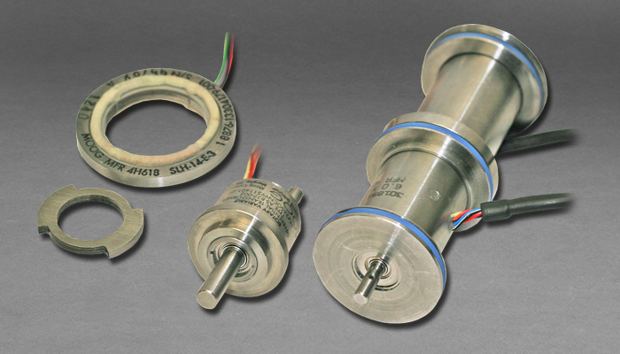
Basic RVDT construction and operation is provided by rotating an iron-core bearing supported within a housed stator assembly. The housing is passivated stainless steel. The stator consists of a primary excitation coil and a pair of secondary output coils.
A fixed alternating current excitation is applied to the primary stator coil that is electromagnetically coupled to the secondary coils. This coupling is proportional to the angle of the input shaft. The output pair is structured so that one coil is in-phase with the excitation coil, and the second is 180 degrees out-of-phase with the excitation coil.
When the rotor is in a position that directs the available flux equally in both the in-phase and out-of-phase coils, the output voltages cancel and result in a zero value signal. This is referred to as the electrical zero position or E.Z. When the rotor shaft is displaced from E.Z., the resulting output signals have a magnitude and phase relationship proportional to the direction of rotation.
Because RVDT’s perform essentially like a transformer, excitation voltages changes will cause directly proportional changes to the output (transformation ratio). However, the voltage out to excitation voltage ratio will remain constant. Since most RVDT signal conditioning systems measure signal as a function of the transformation ratio (TR), excitation voltage drift beyond 7.5% typically has no effect on sensor accuracy and strict voltage regulation is not typically necessary. Excitation frequency should be controlled within +/- 1% to maintain accuracy.
Contact our application engineers for more information and to discuss your specific needs.
Models and Specifications
| Model | Voltage (VRMS)* | Frequency (Hz) | Impedance** | Scale Factor (V/Deg) | Angular Displacement (± Deg.) | Accuracy (± Deg.) | Phase Angle (+/- Deg.) | Impedance | Test Load | Variation with Temp. (Deg. C Max.) | Crosstalk (%) | Weight (oz) |
| Input | Output | |||||||||||
| AS-827-001 | 8.0 | 1,870 | 65 + j475 | 0.061 | 40 | 0.2 | 5 | 78 + j88 | 7,000 pF | 0.05 | N/A | 2.0 |
| AS-827-002 | 8.0 | 1,870 | 65 + j475 | 0.068 | 40 | 0.3 | 5 | 78 + j88 | 7,000 pF | 0.05 | N/A | 2.0 |
| AS-827-003 | 8.0 | 1,870 | 65 + j475 | 0.068 | 40 | 0.3 | 5 | 78 + j88 | 7,000 pF | 0.05 | N/A | 2.0 |
| AS-827-004 | 8.0 | 1,870 | 65 + j475 | 0.061 | 42 | 0.4, 0.6 | 7 | 78 + j88 | 7,000 pF | 0.05 | N/A | 2.0 |
| AS887-001 | 7.0 | 3,000 | 217 + j448 | 0.052 | 30 | 0.25 | 7 | 114 + j103 | 40 Kohms | 0.05 | N/A | 2.0 |
| RV-08-B-05C | 5.7 | 3,500 | 84 + j99 | 0.019 | 80 | 0.50** | 5 | 88 + j361 | 50 Kohms | 0.05 | N/A | 2.0 |
| PRV-15-A-15A | 3.5 | 2,879 | TBD | 0.015 | 37 | 0.2 | 7.5 | 50 ohms | N/A | 0.05 | N/A | 1.0 |